- IBAC
- Network
- Zero-trust
- Kubernetes
Mastering Kubernetes networking: A journey in cloud-native packet management
Master Kubernetes networking with a comprehensive packet walk, and learn how Otterize helps build adaptive Network Policies.
Written By
Nic VermandéPublished Date
Jun 13 2024Read Time
28 minutes
In this Article
Having spent more than half of my career juggling with deep networking technologies, it was naturally the first aspect that caught my eye when exploring Kubernetes. As I dived into the world of containers and orchestrators, I realized that Kubernetes handles networking quite differently from traditional datacenter technologies. Where traditional approaches emphasize infrastructure and make the network fundamental to architecture design from the outset, Kubernetes doesn’t dwell on it.
Instead, it abstracts network management to a significant degree, pushing it to the background to enhance scalability and simplicity. This abstraction is largely achieved through the implementation of the Container Network Interface (CNI), a modular and pluggable design that supports a variety of networking solutions without binding them tightly to the core Kubernetes engine.
This approach not only simplifies networking by abstracting it but also empowers users with the flexibility to “pick what suits their needs.” For those seeking straightforward network setups, a simple CNI like Flannel may suffice. On the other hand, environments requiring enhanced security and visibility might opt for a more sophisticated solution like Cilium. Similarly, for scenarios necessitating hardware integration, tools like MetalLB can be employed to manage load balancing.
Ultimately, Kubernetes remains agnostic to the choice of networking solution, as long as it adheres to the defined standards of the CNI interface, which include the implementation of specific functions in Go:
- AddNetwork: Sets up the network for a container.
- DeleteNetwork: Tears down the network when a container is removed.
- CheckNetwork: Checks the status of the container’s network configuration.
In this blog post, we are going to trace the journey of a network packet in a Kubernetes cluster—from a user making a request to an application, moving through an Ingress Controller, and navigating through the backend application. We'll also see how Otterize enhances security by dynamically generating network policies tailored to actual traffic patterns, providing a practical solution to the unique networking challenges of cloud-native applications.
🚨 Wait! If you want to learn more about these topics, consider the following:
Take control: Our Network Mapping and Network Policy tutorials provide a hands-on opportunity to explore these concepts further.
Stay ahead: Join our growing community Slack channel for the latest Otterize updates and use cases!
Revisiting Kubernetes network architecture and security fundamentals
Before Kubernetes, significant networking innovations helped shape the concept of "software-defined networking" (SDN). Key developments included Nicira's work on OpenFlow and the advent of distributed data planes, which laid the groundwork for advanced network abstraction. OpenStack's Neutron project, for example, offered a flexible, SDN-based approach to manage VMs and cloud infrastructure networking, similar to how Kubernetes later designed its CNI to allow integration with various network providers. Whether the requirement is for simple bridge networks or complex multi-host overlays, CNI plugins integrate these solutions, maintaining network isolation and ensuring that container networking requirements are met efficiently.
These earlier technologies emphasized the importance of flexibility and extensibility in network architecture—core principles that Kubernetes has embraced. By learning from these models, Kubernetes has been able to separate physical network infrastructure from application networking needs, allowing for more dynamic scalability and adaptability to complex environments, including virtual network function virtualization (VNF) and service provider 5G control planes.
Before diving deep into a packet walk, let’s examine the core components of Kubernetes Networking.
Core Components of Kubernetes Networking
Pod networking
Understanding Kubernetes networking begins with its basic building block: Pod Networking. In Kubernetes, every pod receives a unique IP address. With this design, each pod can communicate directly with others across the cluster without complex routing or additional Network Address Translation (NAT), dramatically simplifying the network design.
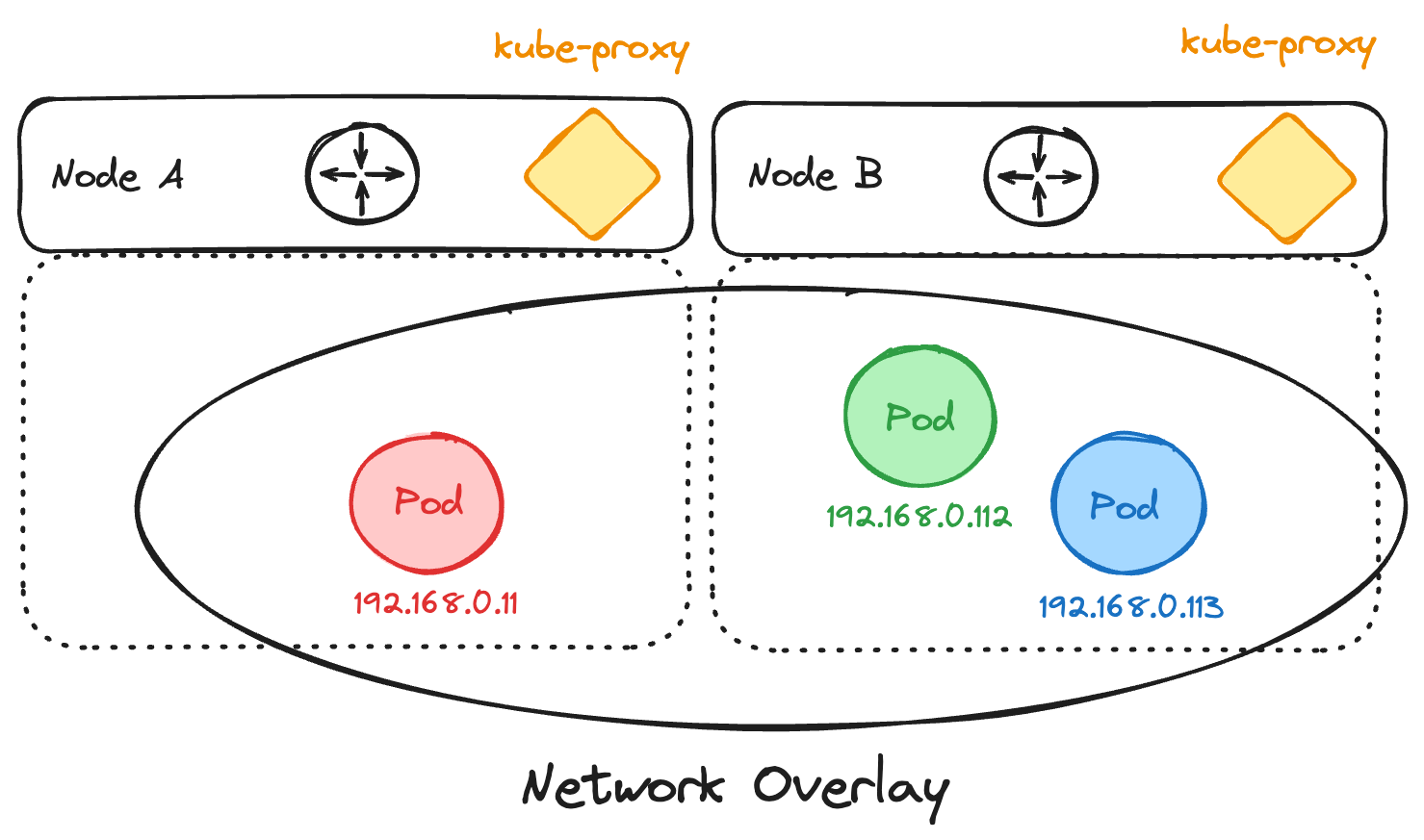
There are two types of networking patterns used in Kubernetes: routed or bridged within an overlay—depending on the chosen CNI vendor and mode. In the routed configuration, each node acts as a router, serving as the default gateway for the pods it hosts locally. Every node owns a dedicated CIDR range and typically peers with the physical network to advertise its routes. In the overlay pattern, traffic is encapsulated by the node, for example using IP-in-IP or VXLAN tunnels. Pod-to-pod traffic appears as if it were flowing within a single CIDR network, in the same L2 segment.
Pod Network with Overlay:
Service Networking
Atop pod networking lies Service Networking. Kubernetes Services act as a stable entry point for accessing a set of pods. This is key because pods are allocated ephemeral IP addresses—their IP changes every time a pod is restarted (technically terminated and re-created). Services provide a consistent address that routes traffic to an active pod, using a ClusterIP as a virtual IP to enable communication between different services within the cluster. ClusterIP is intended for internal cluster traffic only, and relies on a load-balancing mechanism handled by kube-proxy.
Service-Type ClusterIP:
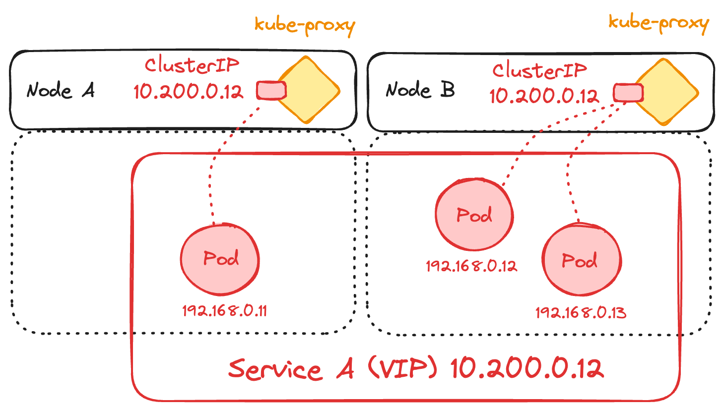
Kube-proxy handles actual traffic routing to pods using different proxy modes—iptables, IPVS, and more recently, nftables. Alternatively, some solutions bypass it entirely, relying on implementations like Open vSwitch (OVS) or eBPF with Cilium. While iptables and IPVS were the original methods, using simple packet filtering rules, nftables offers a more modern approach with potentially better performance and easier rule management. However, as of Kubernetes 1.29, its implementation is still under heavy development and may not yet provide significant enhancements.
In the case of iptables, kube-proxy monitors the Kubernetes control plane for the addition and removal of Service and Endpoint objects, representing the backend pods. When it detects a change, it updates the iptables rules to reflect this in IP address or port mappings. This process allows traffic to be redirected to the correct pods using a round-robin algorithm. However, as the cluster scales, managing these rules can become inefficient, making nftables a potentially more attractive option in the future, or alternative solutions like OVS or eBPF. By default, kube-proxy doesn't prioritize local pods and can seamlessly perform DNAT (Destination Network Address Translation) to a pod located on any node within the cluster.
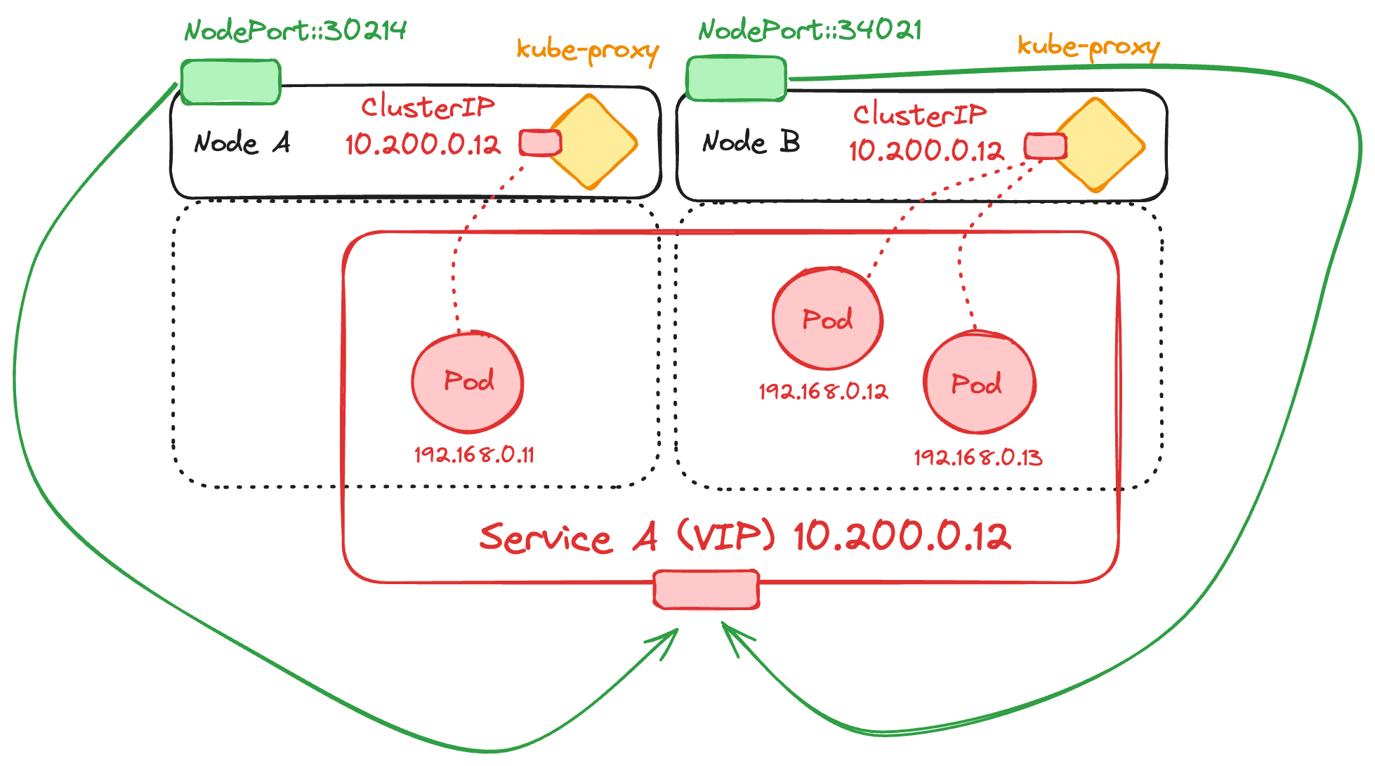
For external access, Kubernetes leverages NodePort and LoadBalancer services. A NodePort service exposes a specific port on all nodes, making the service accessible from outside the cluster at <NodeIP>:<NodePort>. This approach is straightforward but can be limiting as it requires exposing high ports (30000-32767) across all nodes. Also, it may introduce extra latency, as any pod is accessible from any node, increasing the chance of reaching a node that doesn't host the desired pod, resulting in an extra network hop.
Service-Type NodePort:
On the other hand, a LoadBalancer service typically leverages cloud provider capabilities to distribute incoming external traffic efficiently across all active pods. This offers a more robust solution, exposing services through public IP addresses and DNS names while handling higher traffic loads without manual port management. It is also a valid approach for on-premises environments, relying on solutions like MetalLB or integrating with products from networking hardware vendors.
Service-Type LoadBalancer: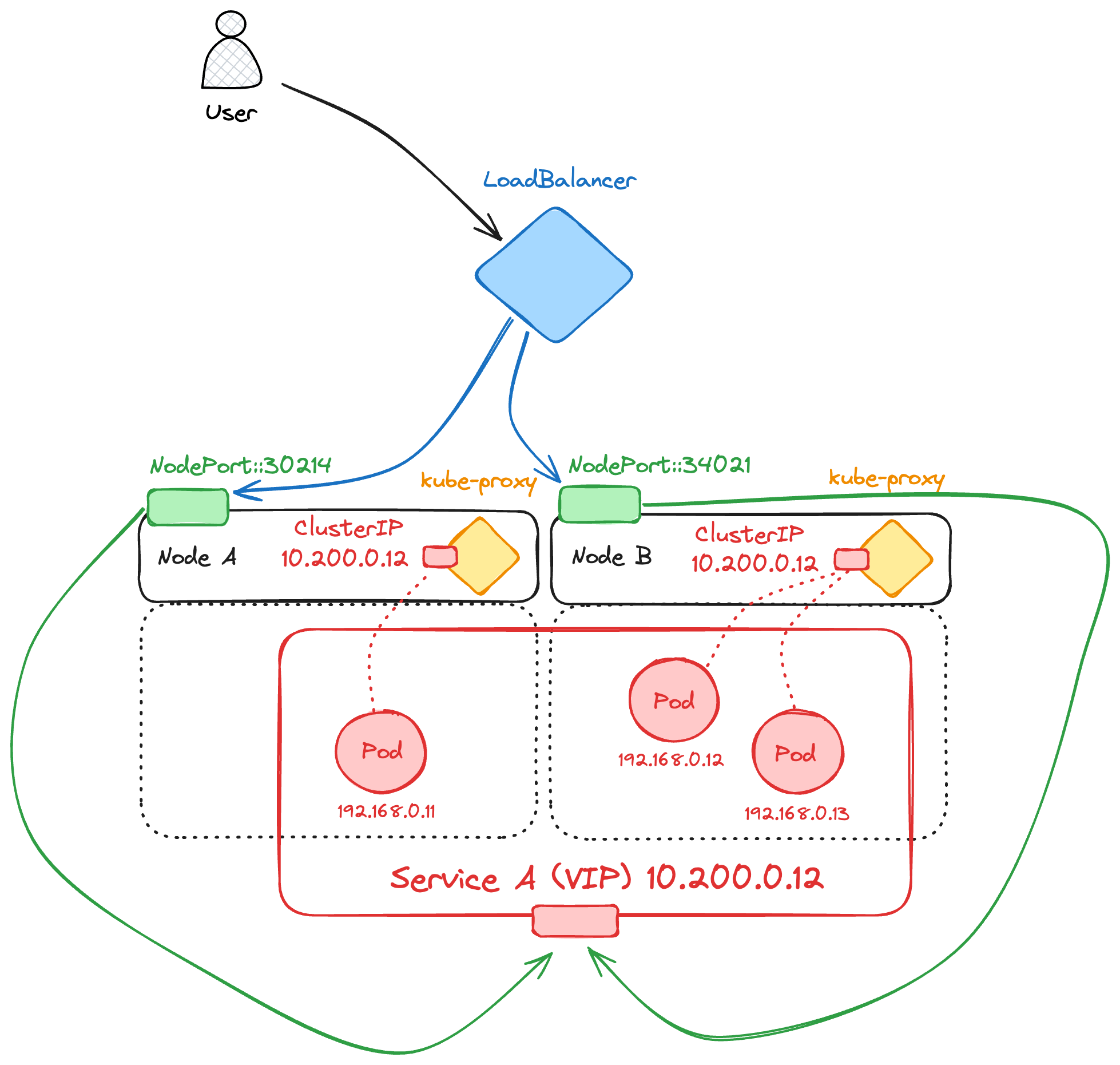
Ingress Controllers offer more specialized control over incoming traffic than NodePort and LoadBalancer services alone. They manage external access to services within the cluster by applying a set of routing rules defined in a Kubernetes Ingress resource (or HTTPRoute in the case of the alternative Gateway API), allowing for more granular management of HTTP and HTTPS traffic.
Ingress Controllers are installed in the cluster as standard Kubernetes Deployments and are often provided by software vendors and open-source projects, such as Traefik, Nginx, or HAProxy. External traffic is steered to the Ingress Controller by exposing its Deployment with a service of type NodePort or LoadBalancer. Typically, when deploying in Hyperscaler environments, a service of type LoadBalancer is used. The Ingress Resource or HTTPRoute configuration determines which internal service should be targeted.
Ingress Controller: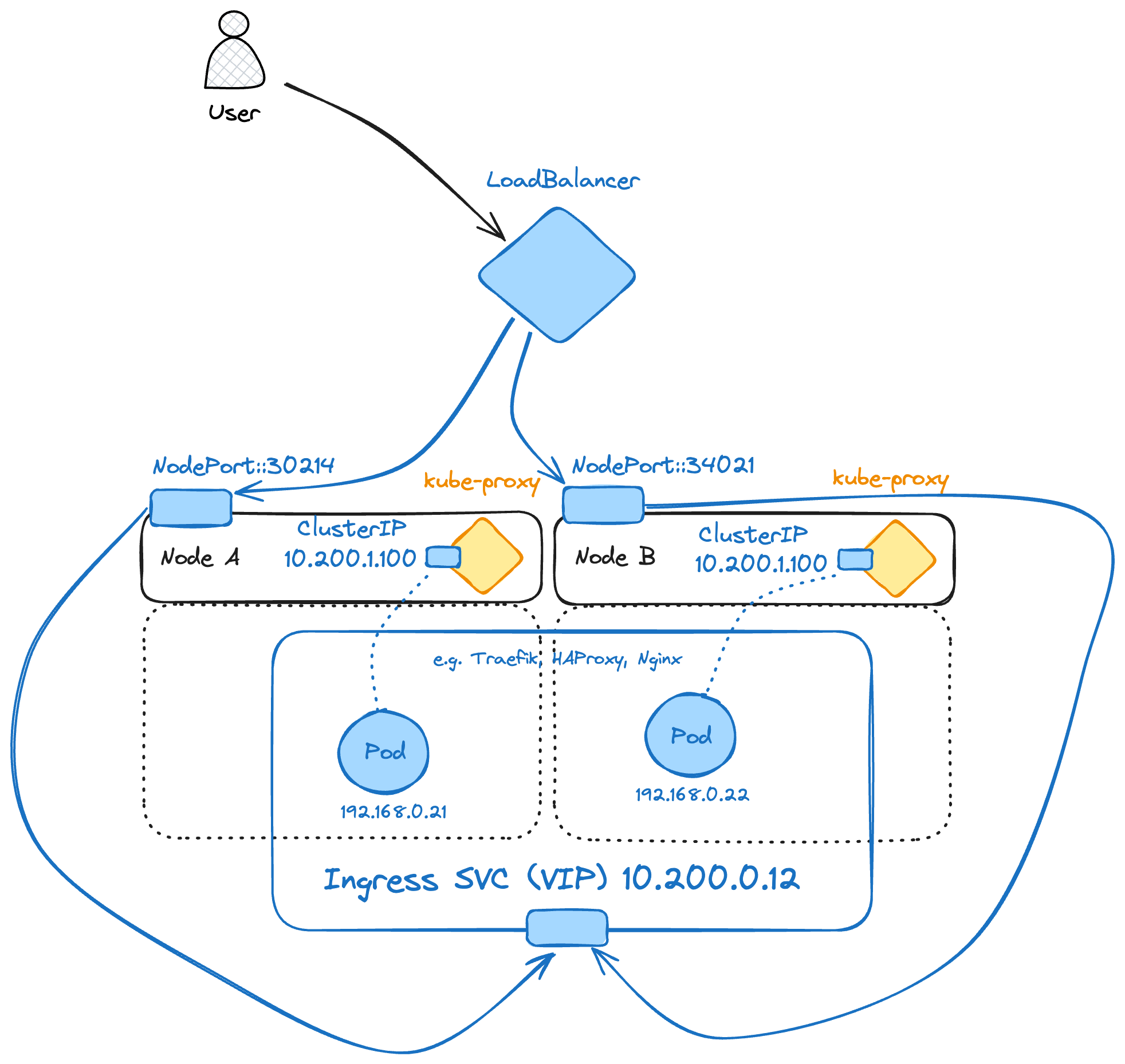
Last but certainly not least—often blamed when networking issues arise—DNS in Kubernetes integrates these components by automating service discovery. Each service in Kubernetes is automatically assigned a DNS name, simplifying the discovery and interaction between services within the cluster. By using easy-to-remember DNS names instead of IP addresses, Kubernetes aligns with user-friendly networking practices while maintaining robust internal communication protocols.
As Kubernetes networking technology has transitioned from basic iptables to sophisticated solutions like nftables and OVS, it demonstrates a clear evolution toward supporting scalable, secure, and efficient operations in distributed environments. This progression highlights Kubernetes' adaptive approach to meeting the complex demands of modern network management, ensuring that as application architectures evolve, the networking foundation remains solid and capable.
Reducing the attack surface with Network Policies
Access Control Lists (ACLs) are not a new concept. They've been used in routers and firewalls for decades to reduce the attack surface of protected assets. Kubernetes implements the same concept with Network Policies, which can be applied to both ingress and egress traffic. Network Policies are stateless, meaning that incoming and outgoing traffic must be considered individually for each flow from the workload perspective.
Network Policies provide fine-grained control over traffic flow between pods, defining which pods can communicate and under what conditions. This is especially important in multi-tenant environments, where multiple applications share cluster resources but must remain isolated.
A Network Policy in Kubernetes is defined using a YAML manifest, specifying the desired rules for ingress (incoming traffic) and egress (outgoing traffic). These policies are enforced at the pod level by the CNI—which must explicitly support Network Policies—and are applied to a group of pods selected by labels. The policies can specify:
- Pod Selector: Determines the group of pods to which the policy applies.
- Ingress Rules: Define the allowed sources of incoming traffic.
- Egress Rules: Define the allowed destinations for outgoing traffic.
- Ports: Specify the ports and protocols allowed for communication.
To illustrate the implementation, let's consider a scenario where we have an application composed of multiple services, each running in its own set of pods. We want to ensure that only specific pods can communicate with each service, minimizing the risk of unauthorized access.
apiVersion: networking.k8s.io/v1
kind: NetworkPolicy
metadata:
  name: allow-specific-ingress
  namespace: default
spec:
  podSelector:
    matchLabels:
      app: myapp
  policyTypes:
  - Ingress
  ingress:
  - from:
    - podSelector:
        matchLabels:
          role: frontend
    ports:
    - protocol: TCP
      port: 80
In the above example, the Network Policy allow-specific-ingress permits traffic only from pods labeled with role: frontend to pods labeled with app: myapp on port 80. This restricts any other pods from communicating with the myapp pods, thereby enhancing security.
Network Policies are a fundamental component of a zero-trust security model within Kubernetes. In a zero-trust architecture, the default stance is to deny all traffic unless explicitly allowed by a policy. This approach limits the potential impact of compromised pods and restricts lateral movement within the cluster.
To implement zero-trust, it is recommended to start with a default deny-all policy and then explicitly define the necessary allowed communications. Here’s an example of a deny-all ingress and egress policy:
apiVersion: networking.k8s.io/v1
kind: NetworkPolicy
metadata:
  name: deny-all
  namespace: default
spec:
  podSelector: {}
  policyTypes:
  - Ingress
  - Egress
This policy applies to all pods in the namespace and denies all incoming traffic. Subsequent policies can then be defined to allow only the required communications, ensuring a minimal attack surface.
But there’s a catch here! Remember that Kubernetes includes an internal DNS for service discovery. So if you plan to use that default DNS service, you must allow every pod to communicate with the Kubernetes DNS service, usually called kubernetes and located within the kube-system namespace. There resulting Network Policy should then be the following:
apiVersion: networking.k8s.io/v1
kind: NetworkPolicy
metadata:
  name: deny-all-allow-dns-egress
  namespace: default
spec:
  podSelector: {}
  policyTypes:
  - Egress
  - Ingress
  egress:
  - to:
    - namespaceSelector: {}
      podSelector:
        matchLabels:
          k8s-app: kube-dns
    ports:
    - protocol: UDP
      port: 53
This policy allows all pods in the default namespace to communicate with the Kubernetes DNS service in any namespace on UDP port 53, enabling necessary DNS resolution while maintaining a zero-trust security posture.
Now that you have all the fundamentals explained, let’s delve into the packet walk.
Packet walk
Application architecture
We’re considering the following voting app application from the docker team, deployed in a 2-node GKE cluster: https://github.com/dockersamples/example-voting-app
The architecture is summarized below: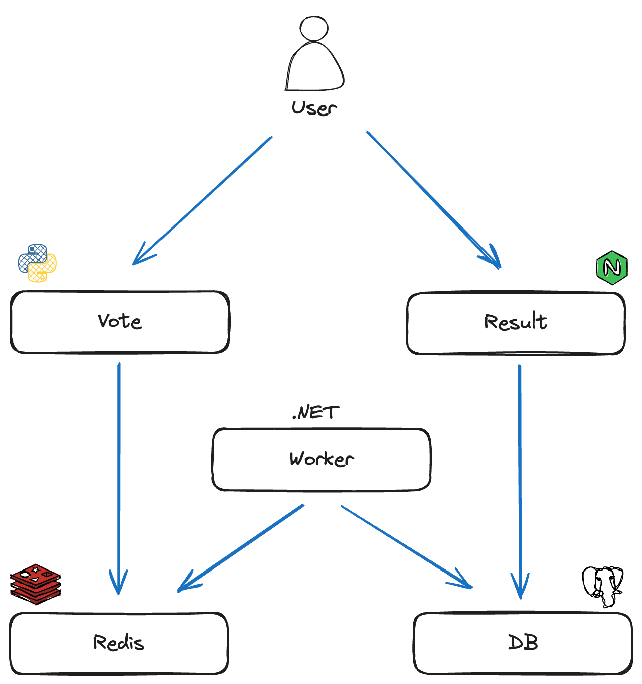
From the user perspective, there are 2 HTTP services accessible from the browser:
- The vote service allows you to vote for cats or dogs.
- The result service displays the current vote ratio.
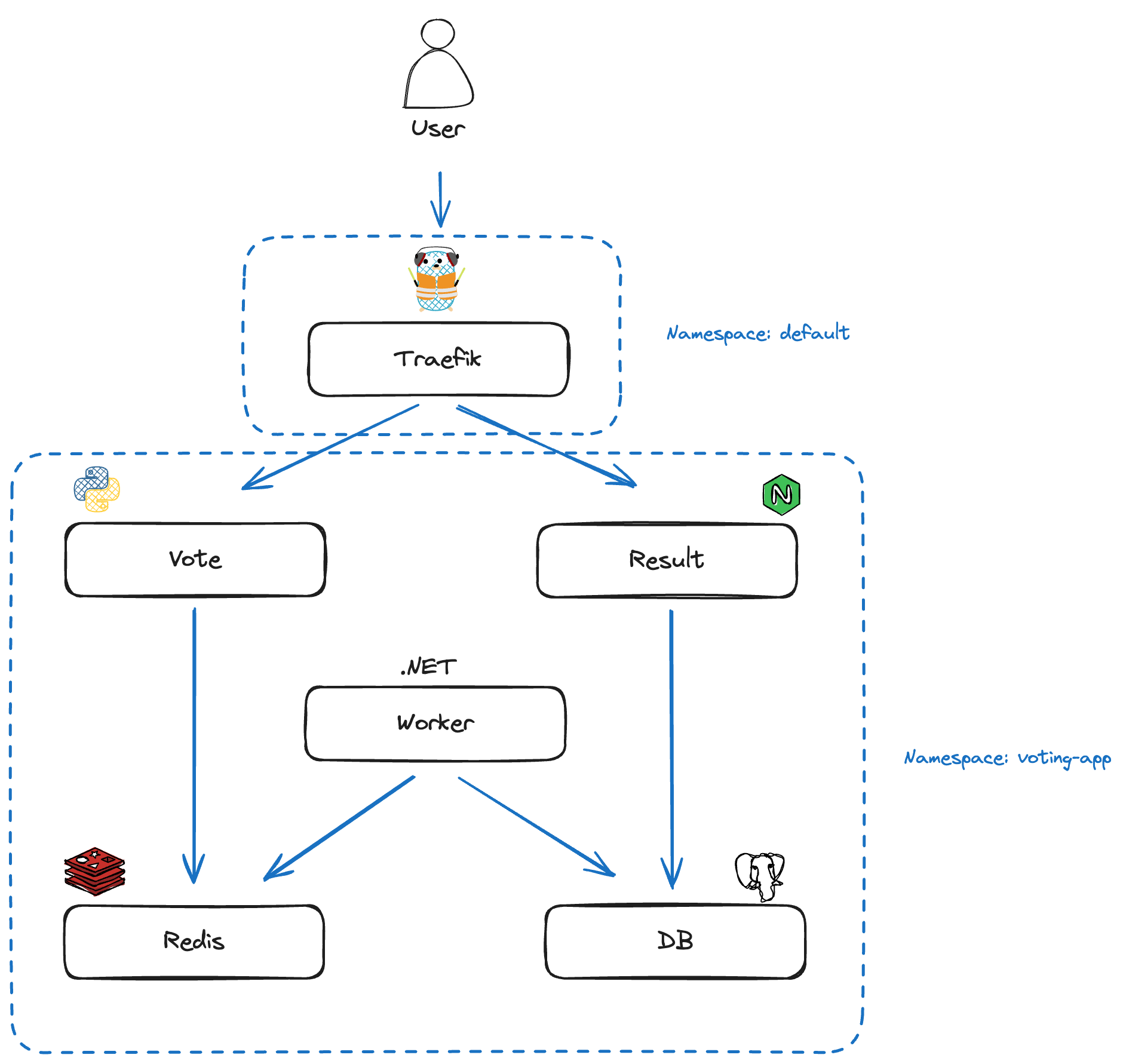
To get a more realistic picture of a production-ready packet flow, we will introduce an Ingress Controller to act as an edge application router to the cluster. For this, we're going to install Traefik using the Helm chart and configure an Ingress resource to expose the vote and result Endpoints via the following domains.
- Vote: vote.gke.local
- Result: result.gke.local
voting-app-ingress.yaml
apiVersion: networking.k8s.io/v1
kind: Ingress
metadata:
  name: voting-app-ingress
  namespace: voting-app
spec:
  ingressClassName: traefik
  rules:
  - host: vote.gke.local
    http:
      paths:
      - backend:
          service:
            name: vote
            port:
              number: 5000
        path: /
        pathType: Prefix
  - host: result.gke.local
    http:
      paths:
      - backend:
          service:
            name: result
            port:
              number: 5001
        path: /
        pathType: Prefix
Note: GKE can automatically configure an HTTP(S) application load balancer when an Ingress resource is created. This is the default behavior, but for educational purposes in this article, we are bypassing this to use Traefik as the Ingress Controller. You can do this by specifying the ingressClassName (set to "traefik") in the Ingress resource configuration.
The Traefik Ingress Controller service is exposed by default as a LoadBalancer service, which automatically provisions a Google Cloud Passthrough Network Load Balancer (GCLB). This type of load balancer forwards traffic directly to the backend nodes without terminating the connections, preserving the original source and destination IP addresses, bypassing NodePort. The service IP address is typically a public IP address allocated by Google Cloud, and the load balancer uses this address to route traffic to the backend Kubernetes nodes according to the configured load-balancing algorithm.
Since I didn’t create any DNS entries for the result and vote services we want to reach via the Ingress Controller, I’ve just added them in my local /etc/hosts file, mapping them to the Traefik ingress public IP address allocated by the load-balancer:
/etc/hosts
35.230.135.55  vote.gke.local
35.230.135.55  result.gke.local
With the above Ingress configuration, the Host HTTP header determines which service the request is redirected to. If the user enters vote.gke.local in the browser, the request is routed to the vote service on TCP port 5000. If they navigate to result.gke.local, the request is routed to the result service on TCP port 5001.
The Ingress Controller is installed in the default namespace as a Kubernetes Deployment with a single replica. After deploying the entire application in GKE with Calico as the CNI (to support Network Policies), the architecture can be summarized with the following diagram:
How to monitor traffic
For this example, I monitored traffic using tcpdump via an ephemeral container that shares the host network and has access to the host file system under /host. You can do this by running the following command:
$ kubectl debug node/<node-name> -it --image=ubuntu
Then update the package sources and install tcpdump and iproute2:
$ apt-get update && apt-get install tcpdump iproute2 -y
The next step is to identify the container network interface ID within the host network stack. To do this, run the following command from another terminal, since the previous command made you enter the ephemeral container shell:
$ kubectl exec -it traefik-658f98b47f-6ttn4 -- cat /sys/class/net/eth0/iflink
30
It will return the network interface ID to look for on the host—”30” in the example above. You can then identify the corresponding network interface on the host. From the ephemeral container, run the following command:
$ ip address | grep 30
30: calib4c02fd8a9e@if3: <BROADCAST,MULTICAST,UP,LOWER_UP> mtu 1460 qdisc noqueue state UP group default qlen 1000
You can now run tcpdump on that interface to monitor the desired traffic for this container. For example:
tcpdump -i calib4c02fd8a9e -nn -vvv -s0 host 10.154.0.9
In the following sections, we'll inspect the traffic between the user and the Ingress Controller, and then between the Ingress Controller and the backend application pod (in both directions).
User to Ingress Controller
Let's break down how the request reaches the right service. When the user types vote.gke.local or result.minikube.local into the browser, the client needs to figure out the IP address behind those names. The Operating System first checks the /etc/hosts file, where these domains are mapped to 35.230.135.55, which is the Traefik service address allocated by the Google load-balancer.
As mentioned before, the Traefik Ingress Controller service is exposed via a LoadBalancer, and can handle incoming requests on ports 80 (HTTP) and 443 (HTTPS). When the browser sends a request to vote.gke.local or result.gke.local, the traffic is routed through the Traefik Ingress Controller, which then directs the request to the appropriate service within the cluster.
Let’s take a look at the flow from the user to the Traefik pod and the detailed path back when trying to connect to http://result.gke.local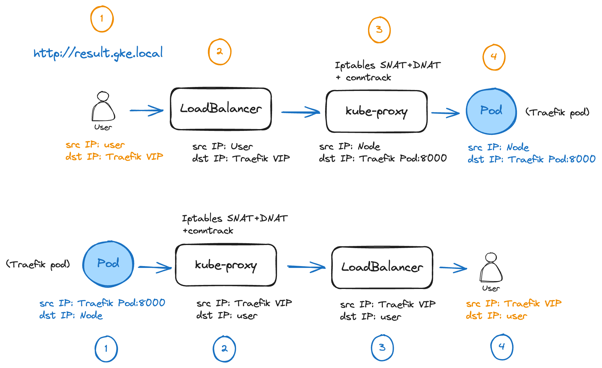
Packet walk from user to Traefik Ingress Controller
1. The user initiates a request:
The process begins with a user making an HTTP request to the URL http://result.gke.local. At this stage, the user's request is directed towards the public Virtual IP address (VIP) of the Traefik Ingress Controller, provided by the Kubernetes LoadBalancer service and provisioned by the GCLB.
2. GCLB forwards the request:
The load balancer receives the incoming request and forwards it to one of the nodes in the Kubernetes cluster. Since the load balancer is operating in passthrough mode, it doesn’t change the source and destination IP addresses. It just forwards the request as-is to one of the healthy backend instances defined in its configuration. But there’s a little catch here! That holds true if GCLB selects the host where the Traefik pod is located (like in the diagram above). If GCLB selects the other host as the destination, where no Traefik pod is running, an extra hop is required to reach the Traefik pod. On the initial receiving host, kube-proxy programs iptables to perform both SNAT and DNAT. The source IP is rewritten as the receiving node IP and the destination IP is changed to that of the Traefik Pod IP. In this way traffic is symmetric and the connection tracking table of the initial receiving host can be matched on the return traffic, where reverse NAT operations are performed.
3. kube-proxy performs SNAT and DNAT with connection tracking:
By default, when a LoadBalancer or NodePort service is configured with externalTrafficPolicy: Cluster (the default setting), external traffic is SNATed (Source Network Address Translated) by kube-proxy upon reaching a node. This is because requests might arrive at a node without any pod Endpoint for the desired service. In this case, kube-proxy forwards traffic to a node with available Endpoints. SNAT ensures that responses return to the original node, enabling correct routing back to the client using its connection tracking table.
Since we kept the default settings, kube-proxy changes the source IP to that of the node. After picking up the only available service Endpoint, it also changes the VIP destination IP address to the actual Traefik pod's IP on port 8000, as defined in the service manifest that maps incoming traffic on service port 80 to container port 8000.
If you need to preserve the client source IP, set externalTrafficPolicy to Local. However, this only routes requests to local Endpoints, potentially causing uneven traffic distribution if pods are not balanced across nodes. If no local Endpoint is available, packets are dropped, triggering TCP retransmission. To avoid this, you can consider using the X-Forwarded-For header or Proxy Protocol for client IP tracking, as these methods maintain traffic distribution across multiple nodes.
Google has simplified this process in GKE, as GCLB handles externalTrafficPolicy: Local differently. Health checks assess all nodes, marking those without local endpoints as unhealthy, thus preventing traffic forwarding and costly retransmissions. This mechanism ensures even traffic distribution and avoids packet loss.
4. The Traefik pod processes the request:
Finally, the packet reaches the Traefik pod, which processes the user's request and forwards it to the backend application pod. (The packet walk for this part will be detailed later in the article).
Packet walk from Traefik Ingress Controller to user (return traffic)
1. The Traefik Pod sends the response:
The Traefik pod sends the response back from the application pod towards the user. It starts its journey back to the user through the same path it arrived.
2. kube-proxy follows its connection tracking table:
By matching the 5-tuple (source IP, destination IP, source port, destination port and protocol), kube-proxy checks its connection table and determines how to craft and route the return packet. In our case, reverse SNAT and DNAT operations are performed.
3. The load balancer sends the response back to the user:
The load balancer receives the response and forwards it to the user's IP.
4. The user receives the response:
The user receives the response, completing the communication cycle.
Ingress controller to backend application service
Under normal circumstances, when a pod calls a ClusterIP service, traffic goes through the local kube-proxy. Kube-proxy implements iptables rules to distribute traffic between available service Endpoints. These rules consider all Endpoints, regardless of whether they are local (on the same node as the source pod) or remote (on different nodes). However, Traefik directly resolves Endpoints without using kube-proxy to provide additional features, such as sticky sessions.
This gave me a bit of a hard time 🤔 understanding the traffic flow, as I was monitoring traffic on the node and couldn’t see kube-proxy processing any packets. This behavior can be changed by passing the CLI option --providers.kubernetesingress.nativeLBByDefault=true in the Traefik container arguments within the Deployment manifest. The traffic below has been observed by setting that parameter, enabling default kube-proxy load-balancing.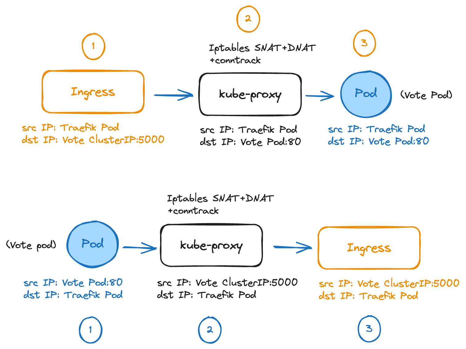
Outgoing traffic from Traefik to the vote service
The Ingress Controller enforces the Ingress resource configuration and selects the vote service, since the HTTP Host header has been set to vote.gke.local. It performs DNAT by rewriting the destination IP to the vote ClusterIP.
The local kube-proxy processes the packet and performs another DNAT operation, rewriting the destination IP to the selected service Endpoint. If multiple pods are backing the service, kube-proxy uses a round-robin algorithm to select an available Endpoint. In our case, there’s a single vote pod, so that Endpoint is used.
The request reaches the vote pod. We can observe that a TCP connection is now established between the Ingress Controller and the backend vote pod on port 80. From the Traefik pod's perspective, a TCP connection is established between a local unprivileged port and the vote ClusterIP on port 80.
Returning traffic from the vote pod to Traefik
The vote pod application returns the HTTP response to the Traefik pod.
The local kube-proxy matches its connection tracking table and performs reverse NAT for source and destination IP addresses.
The Traefik pod receives the packet.
Composing Network Policies
The Ingress Controller enforces the Ingress resource configuration and selects the vote service, since the HTTP Host header has been set to vote.gke.local. It performs DNAT by rewriting the destination IP to the vote ClusterIP.
The local kube-proxy processes the packet and performs another DNAT operation, rewriting the destination IP to the selected service Endpoint. If multiple pods are backing the service, kube-proxy uses a round-robin algorithm to select an available Endpoint. In our case, there’s a single vote pod, so that Endpoint is used.
The request reaches the vote pod. We can observe that a TCP connection is now established between the Ingress Controller and the backend vote pod on port 80. From the Traefik pod's perspective, a TCP connection is established between a local unprivileged port and the vote ClusterIP on port 80.
The vote pod application returns the HTTP response to the Traefik pod.
The local kube-proxy matches its connection tracking table and performs reverse NAT for source and destination IP addresses.
The Traefik pod receives the packet.
Composing Network Policies
The job isn't done yet! Now that we know exactly how traffic flows through our application, it's time to secure it. Considering the earlier application diagram, this is the security perimeter we need to enforce:
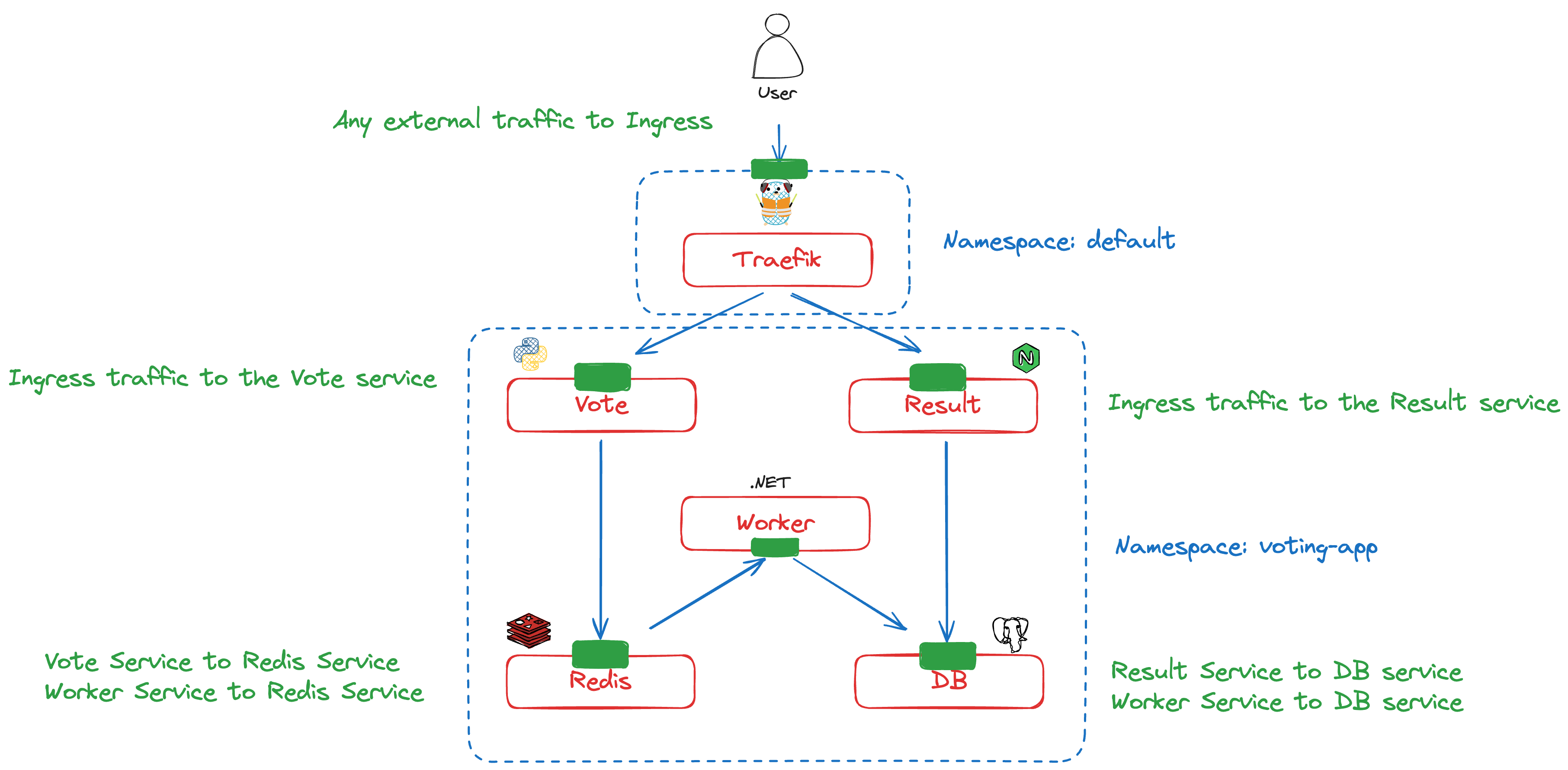
For this article, we'll focus only on ingress network policies. Egress policies can be considerably more complex and deserve their own dedicated article—so stay tuned!
Ideally, we want a way to effectively map actual traffic to the required Network Policies and automatically compose them as the application evolves. This is exactly what we can achieve by combining the Network Mapper and the Client Intents Operator.
Let's see how this works. We'll generate Client Intents to declaratively define the services that application components need to access. Client Intents are simply a list of calls that a client intends to make. This list can be used to configure various authorization mechanisms, such as Kubernetes Network Policies, Istio Authorization Policies, cloud IAM, database credentials, and their respective permissions. In other words, developers declare what their service intends to access.
Using the Otterize CLI, we can generate all Client Intents based on actual traffic patterns detected by the Network Mapper, which leverages information collected by BPF.
$ otterize network-mapper export -n voting-app | kubectl apply -f -
clientintents.k8s.otterize.com/result created
clientintents.k8s.otterize.com/vote created
clientintents.k8s.otterize.com/worker created
These Client Intents, in turn, generate the following Network Policies to protect the application components:
#voting-app namespace
$ kubectl get netpol -n voting-app
NAME                        POD-SELECTOR                                           AGE
db-access                   intents.otterize.com/service=db-voting-app-678928      6d16h
external-access-to-result   app=result                                             6d16h
external-access-to-vote     app=vote                                               6d16h
redis-access                intents.otterize.com/service=redis-voting-app-db26e5   6d16h
#default namespace
$ kubectl get netpol
NAME POD-SELECTOR AGE
external-access-to-traefik app.kubernetes.io/instance=traefik-default,app.kubernetes.io/name=traefik 6d16h
In the voting-app namespace:
- db-access: Enables access from the worker and result services to the database service.
- redis-access: Enables access from the worker and vote service to the redis service.
We can also generate the Network Policies required by the Traefik Ingress Controller to allow external traffic to the vote and result services by specifying the following Helm option when installing Otterize: intentsOperator.operator.allowExternalTraffic=always
This creates the following Network Policies:
- External-access-to-traefik: (default Namespace) Enables access from external users to Traefik.
- External-access-to-result: Enables access from Traefik to the result service.
- External-access-to-vote: Enables access from Traefik to the vote service.
Using Otterize Client Intents, we have generated the 5 Network Policies matching the design depicted on the initial diagram, with no manual task required. As developers, we only need to generate the Client Intents using the Network Mapper, and we can simply attach them to our code as YAML manifests—job done!
As our application evolves, we can also ask Otterize to update our application or Infrastructure-as-Code repository with new Client Intents whenever new services are added or the Network Mapper detects new access patterns. This significantly simplifies CI/CD pipelines and optimizes the DevSecOps process, especially during the staging phase, where we can validate whether these new application patterns are expected. We can then use GitOps principles when deploying to production, incorporating both new application components and their associated security configurations. Suddenly, life becomes much easier for developers, while security teams remain happy!
TL;DR
Kubernetes networking can be complex, but understanding its core components is essential for effective management. This article takes a deep dive into the world of cloud-native networking, exploring concepts like Ingress, microservices communication, and packet walks.
While Network Policies in Kubernetes are essential for securing your applications, manual management is often a headache. Plus, they may not be the most developer-friendly tool, as detailed in this article.
This is where Otterize shines. We automate Network Policy creation and management based on real-world traffic patterns, providing developers with a clear, intuitive way to express their requirements. The result? Stronger security, a smaller attack surface, and streamlined CI/CD pipelines – all without slowing down development. Otterize empowers developers and keeps your security team happy!
Conclusion
In this deep dive, we've explored the busy "highway system" of Kubernetes networking, tracing a packet's journey and highlighting the important role of Network Policies. We've seen how the manual management of these policies can quickly become overwhelming, much like directing traffic without a map.
But just as modern cities rely on intelligent traffic management systems to optimize traffic flow and ensure safety, Otterize provides that same level of automation and control for your Kubernetes environment. Otterize secures IAM workflows within your Kubernetes cluster by automating the creation and maintenance of Network Policies based on real-time traffic patterns, among other capabilities. This ensures your security rules are always up-to-date and effective, adapting dynamically to changing conditions, so your applications are protected by a robust and adaptive security framework.
The cloud-native landscape is constantly evolving, and with it, the threats that organizations face. While AI opens up exciting new possibilities, it also provides malicious actors with advanced tools to exploit vulnerabilities. This escalating threat landscape underscores the importance of reducing the blast radius of potential attacks—something that Otterize achieves by continuously aligning security configurations with the dynamics of your applications, minimizing the impact of any potential breaches.
Embracing tools like Otterize not only simplifies Kubernetes security but also empowers teams to build and maintain secure, resilient, and efficient cloud-native applications. So, take the plunge and explore the depths of Kubernetes networking—with Otterize by your side, you'll confidently navigate the complexities, build a secure infrastructure, and proactively adapt to changing application patterns, ensuring continuous compliance in the face of evolving threats.
💬 Let's discuss!
Shape the future: We value your input! Share your thoughts on which tutorials would be most useful to you. Also, what other networking and IAM security automation scenarios are you interested in? Let us know.
Let's talk: Our community Slack channel is a great place to share your feedback, challenges, and any hiccups you encountered during your experience with Otterize—it’s also where you’ll be able to message me directly with any questions you may have. Let's learn from each other and discover solutions together!
In this Article
Like this article?
Sign up for newsletter updates
Resource Library
Read blogs by Otis, run self-paced labs that teach you how to use Otterize in your browser, or read mentions of Otterize in the media.
- Kubernetes
New year, new features
We have some exciting announcements for the new year! New features for both security and platform teams, usability improvements, performance improvements, and more! All of the features that have been introduced recently, in one digest.
- Kubernetes
First Person Platform E04 - Ian Evans on security as an enabler for financial institutions
The fourth episode of First Person Platform, a podcast: platform engineers and security practitioners nerd out with Ori Shoshan on access controls, Kubernetes, and platform engineering.